
VRRP Concept Guide
 Purpose and Scope
This document explains the concept of Virtual Router Redundancy Protocol, commonly known as VRRP. It is intended for network engineers, deployment teams, support engineers, and documentation teams who need a reusable reference for gateway high availability design.
Overview of VRRP
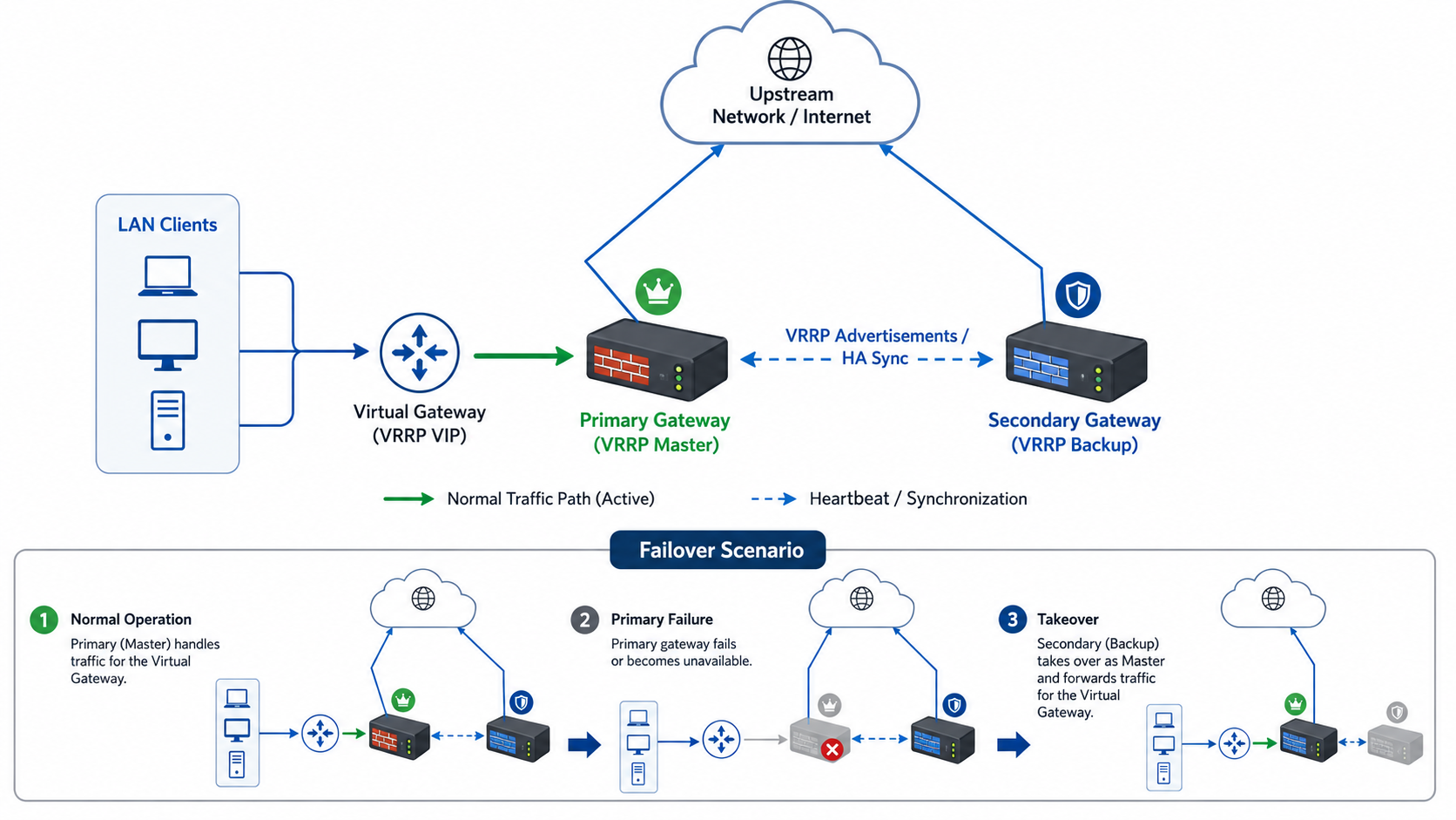
VRRP is a gateway redundancy protocol that allows two or more gateway devices to act together as one logical gateway for LAN clients. The clients use a shared virtual gateway address instead of using the real address of a single physical device.
During normal operation, one device owns the virtual gateway and forwards traffic. This device is called the Master. Another device waits in standby mode and monitors the Master. This device is called the Backup.
If the Master becomes unavailable, the Backup takes over the virtual gateway and starts forwarding traffic. From the client perspective, the default gateway remains the same, which reduces downtime and avoids manual client-side changes.
Why Gateway Redundancy Is Needed
In a standard LAN, every client requires a default gateway to communicate outside its local network. If there is only one gateway and that device fails, all clients lose external connectivity.
VRRP removes this single point of failure by allowing multiple gateway devices to share the same logical gateway. If the active device fails, the standby device automatically becomes active and continues forwarding traffic.
This design is useful in enterprise branches, hotels, campuses, data centers, healthcare networks, banking networks, SD-WAN edge deployments, and any environment where gateway availability is critical.
Core VRRP Components
VRRP uses a small set of core components to provide gateway failover.
The virtual gateway is the shared gateway used by clients. It is owned by the active VRRP device.
The Master is the active device that owns the virtual gateway and forwards client traffic.
The Backup is the standby device that monitors the Master and takes over during failure.
The virtual router group identifies which devices belong to the same redundancy group.
Priority defines which device is preferred to become Master. A higher priority is preferred during normal operation.
Advertisements are heartbeat messages sent by the Master so the Backup can confirm that the Master is still available.
How VRRP Works
When VRRP is enabled, all participating devices join the same virtual router group on the same LAN segment. Each device has a priority value. The device with the highest effective priority becomes the Master.
The Master owns the virtual gateway and sends periodic VRRP advertisements. Backup devices listen for these advertisements. As long as the advertisements are received, the Backup devices remain standby.
If the Backup device stops receiving advertisements, it assumes the Master is unavailable. After the failover timer expires, the Backup becomes the new Master, takes ownership of the virtual gateway, and begins forwarding traffic.
Client devices continue using the same gateway because the virtual gateway has moved to the new active device.
VRRP Protocol and Port Behavior
Key point: This section explains operational behavior and design considerations without environment-specific addresses.
VRRP does not use a TCP port or UDP port. It is not a port-based protocol like web access, SSH, RADIUS, or IPsec control traffic.
VRRP runs directly on top of IP using protocol number 112. Because of this, security policies or packet filters should allow the VRRP protocol itself, not a TCP or UDP port.
VRRP advertisements are local multicast messages. They are designed to stay inside the local Layer-2 segment and are not normally routed across networks.
When troubleshooting, engineers should check whether the switch, firewall policy, or security filtering is blocking VRRP protocol traffic between the participating devices.
Layer-2 and Switch Requirements
Key point: This section explains operational behavior and design considerations without environment-specific addresses.
VRRP peers must be connected through the same Layer-2 broadcast domain for the interface where VRRP is operating. In practical terms, both devices should be connected to the same LAN segment or the same VLAN.
If the devices are placed in different VLANs, different Layer-3 segments, or isolated switch domains, they will not participate correctly in the same VRRP group.
For access-port deployments, both gateway interfaces should be in the same VLAN. For trunk deployments, the VLAN where VRRP is configured must be allowed on both trunk ports.
Switches should not block VRRP multicast advertisements. Spanning Tree, port-security, storm-control, multicast-control, or filtering policies should be reviewed if VRRP behavior is unstable.
Master and Backup Election
VRRP uses priority to decide which device should become Master. The device with the highest effective priority is preferred.
In a typical active-standby design, the preferred Primary device is configured with a higher priority, while the Secondary device is configured with a lower priority.
If the Primary device fails, the Secondary becomes Master. If the Primary recovers, the final role depends on whether preemption is enabled or disabled.
Priority can also be dynamically adjusted based on health checks, interface tracking, or SLA tracking depending on the device implementation.
Advertisement and Timer Behavior
The Master sends VRRP advertisements at a configured interval. The Backup uses these advertisements as a heartbeat mechanism.
A shorter advertisement interval can reduce failover time, but it may increase control-plane sensitivity and should be tested carefully. A longer interval is less sensitive but can increase failover time.
The failover time depends on advertisement interval, missed advertisement detection, device processing, switch forwarding behavior, address learning updates, and optional health tracking logic.
During failover, a small number of packets may be dropped while the Backup becomes Master and the network updates forwarding information.
Failover and Recovery Flow
In normal operation, the Primary device is Master, owns the virtual gateway, and forwards user traffic. The Secondary device remains Backup and monitors the Master.
When the Master fails or becomes unhealthy, the Backup stops receiving valid advertisements or detects that its priority is now higher. It changes state from Backup to Master.
The new Master announces ownership of the virtual gateway. LAN clients continue using the same gateway address. After the network updates its forwarding information, traffic resumes through the new Master.
If the original Primary recovers, the network either stays on the current Master or fails back to the preferred device depending on the preemption design.
Preemption Concept
Key point: This section explains operational behavior and design considerations without environment-specific addresses.
Preemption controls whether a higher-priority device should automatically take back the Master role after it becomes healthy again.
When preemption is enabled, the preferred device automatically returns to Master after recovery. This keeps the preferred traffic path predictable.
When preemption is disabled, the current Master can remain active even after the preferred device recovers. This avoids an automatic failback event and gives engineers more operational control.
Preemption should be selected based on business policy, maintenance process, and tolerance for a brief failback interruption.
SLA and Interface Tracking with VRRP
Key point: This section explains operational behavior and design considerations without environment-specific addresses.
Basic VRRP primarily detects whether the Master is advertising. However, a device can still be powered on and connected to the LAN while its upstream path is broken.
SLA tracking improves failover behavior by checking reachability beyond the local device. If the monitored path fails, the device priority can be reduced, allowing another device to become Master.
Interface tracking monitors the physical state of an interface such as an uplink or WAN port. If the tracked interface goes down, the device priority can be reduced or failover can be triggered.
SLA tracking detects upstream reachability issues. Interface tracking detects physical link failures. Using both together provides stronger failure detection than using only one method.
VRRP and HA Sync
Key point: This section explains operational behavior and design considerations without environment-specific addresses.
VRRP and HA synchronization are related but serve different purposes.
VRRP handles virtual gateway ownership, Master and Backup state, and gateway failover.
HA synchronization handles peer coordination, DHCP lease synchronization, session information, state sharing, or configuration synchronization depending on the platform capability.
The HA sync link should normally be dedicated to synchronization and heartbeat functions. It should not be used for regular user traffic unless a specific advanced design requires it.
Conclusion
VRRP is a foundational protocol for gateway high availability. It allows multiple gateway devices to provide one logical default gateway to LAN clients.
The active device owns the virtual gateway and forwards traffic. The standby device monitors the active device and takes over when failure conditions are detected.
A reliable VRRP design requires correct Layer-2 connectivity, proper priority planning, appropriate health tracking, and complete routing and policy readiness on both devices.
When implemented correctly, VRRP helps reduce downtime and provides a stable gateway redundancy mechanism for enterprise and branch networks.