
Power over Ethernet (PoE) Explained: Standards, Extenders, and Switch Power Budgets
Power over Ethernet (PoE) is a networking technology that transmits electrical power alongside data over standard twisted-pair Ethernet cables to Powered Devices (PDs) such as wireless access points (APs), IP cameras, and VoIP phones.
By delivering both power and connectivity over a single RJ45 cable, PoE eliminates the need for dedicated electrical outlets and AC power adapters at every device location—simplifying installations and reducing infrastructure costs.
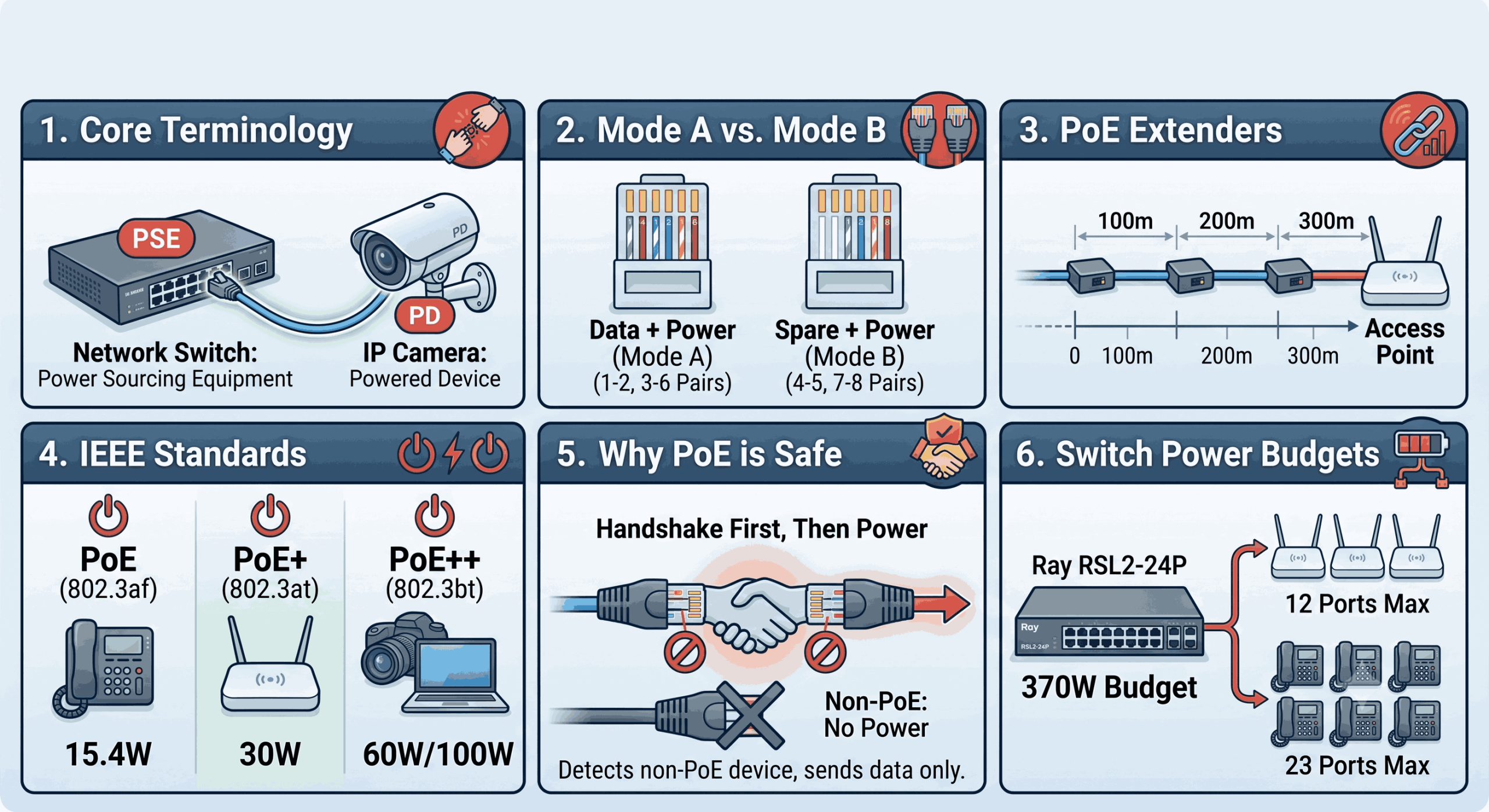
1. Core Terminology: PSE vs. PD
1. Core Terminology: PSE vs. PD
To understand how PoE systems work, it helps to start with the two fundamental device roles:
-
Powered Devices (PDs): Any network edge device that receives power over the Ethernet cable (e.g., Wireless APs, VoIP phones, and IP cameras).
-
Power Sourcing Equipment (PSE): Any device that injects electrical power onto the Ethernet cable to supply a connected PD.
End-Span vs. Mid-Span PSE
PSE devices are categorized by where they sit in the network topology:
-
End-Span PSE: Typically a PoE-enabled Network Switch. Because the switch itself provides power directly from its ports, no extra power hardware is needed between the switch and the edge device.
-
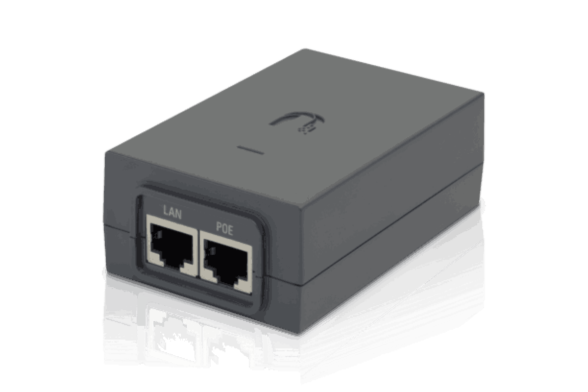
Mid-Span PSE: Used when connecting a non-PoE network switch to a PoE-enabled PD. A mid-span device is installed “in the middle” of the link to inject power without interfering with the data stream. The most common mid-span PSE is a standalone PoE Injector.
2. How PoE Transmits Power: Mode A vs. Mode B
Standard twisted-pair Ethernet (Cat5e/Cat6) has a maximum transmission distance of 100 meters (328 feet) before signal degradation occurs. Within that distance, PoE delivers DC power using one of two wiring configurations:
-
PoE Mode A: Delivers power over data pairs 1–2 and 3–6. Pins 1 & 2 carry positive (+) DC voltage, while pins 3 & 6 carry negative (-) DC voltage. End-span devices like PoE switches typically use Mode A.
-
PoE Mode B: Delivers power over spare pairs 4–5 and 7–8. Pins 4 & 5 carry positive (+) DC voltage, while pins 7 & 8 carry negative (-) DC voltage. Standalone mid-span devices like PoE injectors and extenders usually use Mode B.
3. Extending the 100-Meter Limit: PoE Extenders
While standard Ethernet data cables are limited to 100 meters (328 feet), PoE Extenders (Repeaters) can push both data and power beyond that boundary.
A PoE extender acts as a mid-span PSE: it receives data and power from an upstream switch or injector, consumes approximately 4–5 watts to power its own internal circuitry, and regenerates the data signal while passing the remaining power down the line to the next device.
Example: If you connect a PoE extender to an IEEE 802.3at (PoE+) injector delivering 25W, the extender uses roughly 5W, leaving 20W available for your connected Ray Access Point, VoIP phone, or camera.
By daisy-chaining multiple extenders, you can power an edge device located significantly farther than the standard 100-meter limit:
| Extenders Used | Total Distance (m / ft) | Power Input from PSE | Extender Power Draw | Max Power Available to PD |
| 1 | 200 m / 656 ft | 25 W | 5 W | 20 W |
| 2 | 300 m / 984 ft | 20 W | 5 W | 15 W |
| 3 | 400 m / 1,312 ft | 15 W | 5 W | 10 W |
| 4 | 500 m / 1,640 ft | 10 W | 5 W | 5 W |
4. IEEE PoE Standards & Specifications
4. IEEE PoE Standards & Specifications
As networking edge devices have evolved—from low-power VoIP phones to high-performance Wi-Fi 6/7 access points and laptops—the IEEE has expanded PoE standards to support higher power budgets. Today, modern switches can deliver anywhere from 15.4W to over 70W per port.
Comparison of IEEE 802.3 Standards
| Specification | PoE (Type 1) | PoE+ (Type 2) | PoE++ (Type 3) | PoE++ (Type 4) |
| IEEE Standard | 802.3af | 802.3at | 802.3bt | 802.3bt |
| Max. Power Per Port (PSE) | 15.4 W | 30 W | 60 W | 100 W |
| Max. Power to Device (PD) | 12.95 W | 25.5 W | 51 W | 71 W |
| PSE Port Voltage Range | 44–57 V | 50–57 V | 50–57 V | 52–57 V |
| PD Voltage Range | 37–57 V | 42.5–57 V | 42.5–57 V | 41.1–57 V |
| Twisted Pairs Used | 2-pair | 2-pair | 4-pair | 4-pair |
| Supported Cable | Cat3 or better | Cat5 or better | Cat5 or better | Cat5e or better |
5. Why PoE is Inherently Safe
5. Why PoE is Inherently Safe
A common concern is whether plugging a non-PoE device (such as a standard laptop or unpowered network interface) into a PoE switch will damage the hardware. IEEE 802.3-compliant PoE is completely safe.
Before a PSE sends full operating power down the cable, it initiates a low-voltage handshake procedure:
-
Detection: The switch checks whether the connected device is a standard PoE PD.
-
Classification: If a PD is detected, the switch determines its power class and required wattage.
-
Power Delivery: Only after a successful handshake does the switch apply full voltage to power up the device. If the handshake fails or an unpowered device is detected, no power is sent.
6. Cabling Best Practice: Avoid CCA Cable
When deploying PoE, always use 100% solid copper cabling rather than Copper-Clad Aluminum (CCA).
Aluminum has significantly higher DC resistance than copper. In PoE installations, higher resistance causes:
-
Greater voltage drop over distance, leaving less power for the PD.
-
Excessive heat dissipation inside cable bundles, which can degrade insulation and create safety hazards.
Rule of Thumb: While CCA cable may be cheaper and acceptable for short, data-only runs, demand 100% copper network cable from your supplier for any PoE application.
7. Understanding Switch Power Budgets
A switch’s PoE Power Budget is the maximum total power available across all PoE ports combined. Importantly, a switch’s total budget is often less than the sum of every port running at maximum power simultaneously.
Case Study: Ray Switch Model RSL2-24P
Let’s examine the Ray RSL2-24P, a 24-port L2+ Cloud-Managed PoE+ switch with a total PoE budget of 370 Watts.

- 24-Ports 4 SFP L2+ Cloud-Managed PoE+ Switch
- Ray L2+ Cloud Managed Switch
- 24 Port 10/100/1000T 802.3af/at PoE+ Ports
- 4 Port Gigabit SFP
- 370 watts PoE Power Budget
- 3 Year Warranty
Powering 802.3at PoE+ devices on Ray RSL2-24P switch with 370W PoE Power Budget:
Consider Powering 802.3at PoE+ Ray Access Points using Ray RSL2-24P Switch with a PoE Power Budget of 370W.
802.3at supplies 30W to the Ray AP. so in this case (Switch Budget ÷ 802.3at PoE+ power requirement.)
To Calculate No. of PoE ports== (370W ÷ 30W) = 12.3
In this case the maximum number of 802.3at PoE+ ports that can be powered by our switch is 12ports.
Meaning out of the 24Ports on the switch, we can power a maximum of 12 switch ports connected to 802.3at PoE+ Ray Access Points.
Powering 802.3af PoE devices on Ray RSL2-24P switch with 370W PoE Power Budget:
Consider powering 802.3af PoE AVAYA VoIP Phones using Ray RSL2-24P Switch with a PoE Power Budget of 370W.
802.3af supplies 15.5W to VoIP Phones. so in this case (Switch Budget ÷ 802.3af PoE power requirement.)
To Calculate No. of PoE ports==(370W ÷ 15.5W) = 23.8
In this case the maximum number of 802.3af PoE ports that can be powered by our switch is 23ports.
Meaning out of the 24Ports on the switch, we can power a maximum of 23 switch ports connected to 802.3af PoE VoIP Phones.