SD-WAN SLA and Best Path Configuration Guide
This document describes the SD-WAN SLA Configuration and SD-WAN Best Path Rule Configuration used for intelligent WAN monitoring, SLA-based performance evaluation, and dynamic Best Path selection within Ray environments.
1. SD-WAN SLA Configuration
The SD-WAN SLA (Service Level Agreement) Configuration continuously monitors WAN link quality and evaluates WAN performance using latency, jitter, packet loss, and connectivity checks.
The SLA engine calculates WAN scores dynamically and provides input to the Best Path engine for WAN selection and failover decisions.

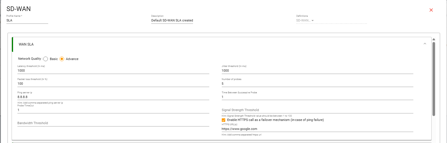
WAN SLA – Field-by-Field Explanation
Understand each WAN SLA setting and how it affects link quality monitoring.
1. Network Quality
Current Value: Advance
This enables detailed SLA monitoring parameters. In Advance mode, the device allows configuration of latency, jitter, packet loss, probe count, timeout, bandwidth threshold, and failover checking options.
2. Latency Threshold
Current Value: 50 ms
This is the maximum allowed network delay for the WAN link. If the latency goes above 50 ms, the WAN link may be treated as poor or degraded. Lower latency is important for real-time applications like voice, video conferencing, remote access, and business applications.
3. Jitter Threshold
Current Value: 5 ms
Jitter is the variation in packet delay. The configured threshold is 5 ms, which means the WAN link should maintain very stable delay. High jitter can affect voice and video traffic, causing call drops, lag, or poor media quality.
4. Packet Loss Threshold
Current Value: 0%
This means no packet loss is allowed on the WAN link. Even a small amount of packet loss can mark the link as degraded. This setting is very strict and is useful when high-quality connectivity is required.
5. Number of Probes
Current Value: 3
The device sends 3 test probes before deciding the quality of the WAN link. These probes help the device measure reachability, latency, packet loss, and overall link health.
6. Ping Server IP
Current Value: 8.8.8.8
This is the destination IP used to test WAN reachability and quality. The device sends SLA probes to this IP through the WAN link. Multiple ping server IPs can be added using comma-separated values.
Example:
8.8.8.8,1.1.1.17. Time Between Successive Probe
Current Value: 0.3 sec
This defines the time gap between each SLA probe. In this case, the device waits 0.3 seconds between each probe. A smaller value gives faster detection, but it may also make the system more sensitive.
8. Probe Timeout
Current Value: 0.3 sec
This is the maximum time allowed for each probe response. If the response does not come within 0.3 seconds, the probe is considered failed. This helps the system quickly detect slow or unreachable WAN links.
9. Bandwidth Threshold
Current Value: 30
This defines the minimum expected bandwidth on the WAN link. The unit depends on the system design, commonly Mbps. If the available bandwidth goes below this threshold, the WAN link may be considered less suitable for traffic forwarding.
10. Signal Strength Threshold
Current Value: Blank
This option is mainly used for SIM, LTE, or 5G WAN links. It checks the cellular signal quality before allowing the link to be used. For wired WAN links, this field can usually be left blank.
11. Enable HTTPS Failover Mechanism
Current Value: Disabled
This option is used as a backup checking method when ping fails. Since it is disabled, the device will not verify internet connectivity using HTTPS if the ping check fails. If ICMP/ping is blocked by the ISP or upstream network, enabling this option can help avoid false WAN failure detection.
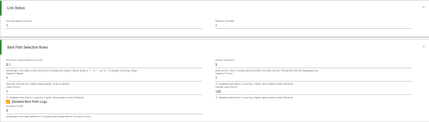
Ray Device – Best Path Selection Rules
This section explains how the Ray device compares WAN link quality and decides when traffic should be switched from the current WAN path to a better available path.
1. Minimum Improvement to Switch
Current Value: 0.1
This value defines how much better the challenger WAN link must be compared to the current active WAN link before the Ray device performs a path switch.
The WAN score range is generally from -1 to +1. In this range, a value of 0.1 is already considered a strong margin.
This prevents unnecessary switching when two WAN links have almost similar quality.
2. Reaction Speed
Current Value: 1
Reaction Speed controls how quickly the Ray device reacts to WAN quality changes.
A higher value makes the device react faster when link quality changes. A lower value makes the system calmer and more stable.
With the value set to 1, the system will react normally and avoid overly aggressive switching.
3. Jitter Priority
Current Value: 1
Jitter Priority defines how much influence jitter has during WAN score calculation.
Jitter means variation in packet delay. It is important for real-time traffic such as voice, video calls, and online meetings.
A value of 0 disables jitter from scoring. A higher value gives jitter more importance in the best path decision.
4. Detailed Best Path Logs
Current Value: Enabled
This option enables detailed logs for best path decision-making.
When enabled, the Ray device records detailed information about WAN score calculation, path comparison, and switching decisions.
This is useful for troubleshooting, analysis, and understanding why the device selected or changed a WAN path.
5. Success Cycles
Current Value: 3
Success Cycles defines how many consecutive cycles the challenger WAN link must remain better before the Ray device switches traffic to it.
With the value set to 3, the challenger WAN link must stay better for 3 continuous cycles before traffic is moved.
This helps avoid unnecessary switching caused by temporary link improvement.
6. Switch Cooldown
Current Value: 3
Switch Cooldown defines how many cycles the Ray device should wait after performing a switch before considering another voluntary switch.
With the value set to 3, the device waits for 3 cycles after switching before making another normal path change.
This prevents frequent path flapping. However, forced failover can still bypass this cooldown if the active link fails.
7. Latency Priority
Current Value: 1
Latency Priority defines how much influence latency has in WAN score calculation.
Latency means network delay. Lower latency is better for real-time and business-critical traffic.
A value of 0 disables latency from scoring. A higher value gives latency more importance in selecting the best WAN path.
8. Packet Loss Priority
Current Value: 100
Packet Loss Priority defines how much influence packet loss has in WAN score calculation.
The current value is 100, which means packet loss has very high importance in best path selection.
This is useful because packet loss directly affects application performance, voice/video quality, and tunnel stability. If a WAN link has packet loss, the Ray device will strongly prefer another better path.
The current configuration prioritizes packet loss heavily during WAN score calculation. Even small packet-loss conditions can reduce WAN score significantly and trigger Best Path changes.
How It Works
The Ray device continuously monitors all available WAN links and calculates a quality score for each link based on configured SLA parameters such as latency, jitter, packet loss, and other priorities.
After calculating the scores, the device compares the current active WAN link with the challenger WAN link. If the challenger link is better by at least the configured Minimum Improvement to Switch value, and it remains better for the configured Success Cycles, the Ray device selects it as the new best path.
After switching, the Switch Cooldown timer prevents frequent path changes. This keeps traffic stable and avoids unnecessary WAN flapping.
2. SD-WAN Best Path Rule Configuration
The SD-WAN Best Path Rule Configuration defines how traffic is classified and dynamically routed across multiple WAN interfaces based on SLA evaluation and WAN scoring.
The Best Path engine continuously compares WAN health and selects the optimal WAN link for traffic forwarding.

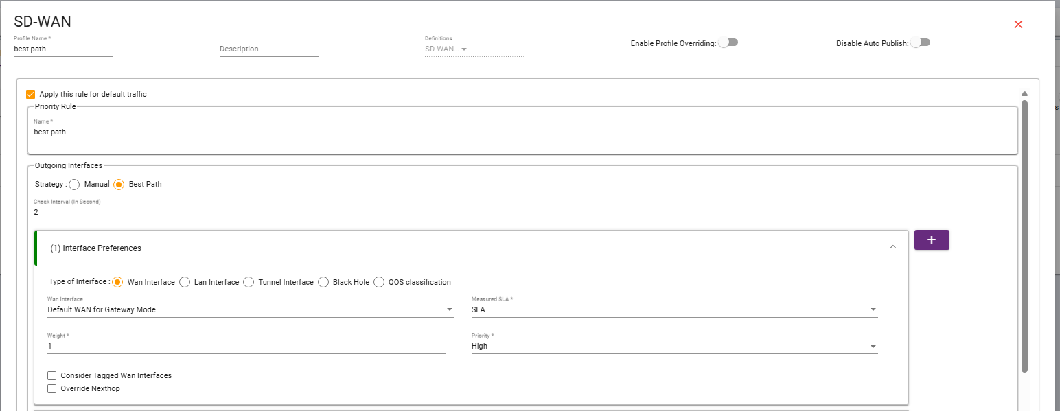
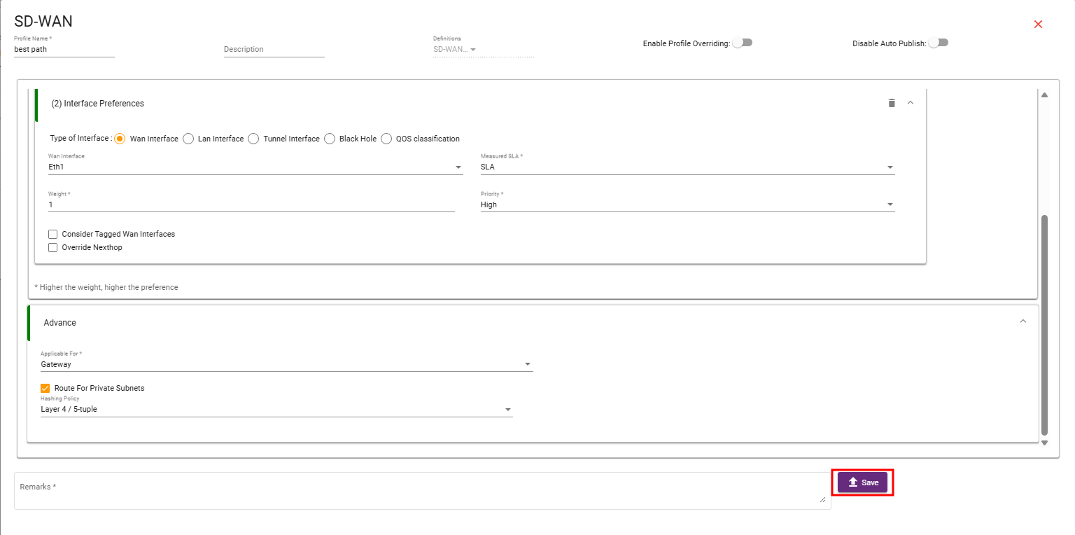
The configuration supports intelligent failover, failback, and dynamic WAN steering.
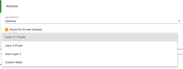
1. Layer 4 / 5-Tuple
Traffic classification is performed using:
• Source IP
• Destination IP
• Source Port
• Destination Port
• Protocol
This provides application-aware routing and session persistence.
2. Layer 3 IP Pair
Traffic classification uses:
• Source IP
• Destination IP
Ports are ignored. This method provides lightweight WAN distribution.
3. Inner Layer 3
Used mainly for:
• IPsec
• WireGuard
• GRE
• VXLAN
• SD-WAN Overlay Tunnels
Traffic classification is performed using inner tunnel traffic.
4. Custom Fields
Traffic is classified using:
• DSCP
• VLAN ID
• Application ID
• User Groups
• Policy Tags
This enables advanced policy-based WAN routing.
Conclusion
The SD-WAN SLA and Best Path Rule Configuration together provide intelligent WAN monitoring, SLA-driven path selection, dynamic failover, and optimized traffic steering across multiple WAN interfaces. The implemented Best Path mechanism ensures improved network reliability, WAN stability, and application-aware traffic routing in enterprise SD-WAN environments.